
Introduction

The goal of this project was to create a circuit that would monitor a copiers three sensors, and if two of the sensors that are next to eachother detect a jam, then the circuit will show the jam and turn the motor back on. And you should be able to reset the copier once the jam has been cleared.
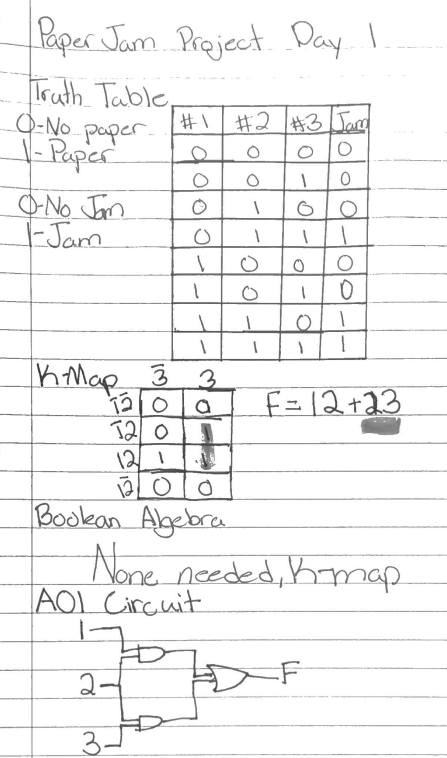
Day 1
|
Boolean Algebra
'123+12'3+123 '123+12('3+3) '123+12 2('13+1) 2(3+1) 12+23 |
Day 2

It was not hard to implement the flip flop into my logic expression, all I had to do was make the output of my logic expression the clock/input of the D Flip Flop. The clock tells the flip flop what the output should be. The reset acts as an off switch for Q and the set acts as an on switch for notQ. The switches act as sensors for pieces of paper in different spots throughout the machine. I did not use any resistors in my circuit and it did not affect the outcome. The AOI circuit tells the Flip Flop when to activate the buzzer and when not to activate the buzzer. We have a flip flop so that we do not need multiple outputs from the AOI circuit, it also acts as an event detector.
Day 3

We need the the motor driver because the power source does not provide mechanical energy and the motor drive converts the energy into mechanical energy and provides a power boost to spin the motor. We had to use a second breadboard and had to power the board using the first board, and put the chip and the motor on that board. It connects to the motor led and uses that as an input to control whether or not the motor turns on.
Conclusion
In order to design my circuit I built a k-map of the possible combinations to find the simplest equation to create my circuit with. Once that was done I used AOI circuit logic to make that equation into a circuit. I then built the circuit in multisim and used the output as the clock/input for the D Flip-Flop gate. Then I created the circuit that my teacher showed me in order to set up the reset "button" for the entire circuit, which essentially turned the motor back on and turned the jam alarm off. I then used that circuit as a template to create a working version of my circuit using tinkercad. The first thing I learned from this assignment was how to use the motor driver chip in tinkercad. The second thing I learned was how I could use the Flip Flop gates in a real circuit rather than just understanding how they work. And finally the third thing that I learned from this project were the issues that can pop up when using multisim and how I can fix those issues without having to ask for help everything. I am starting to feel very comfortable with multisim and tinkercad and I believe that I am really starting to understand how they work.
